A waveguide is a structure that restricts the motion of waves, disallowing propagation in certain directions, and thus concentrating the energy of the wave to propagate in specific other directions. An example of a waveguide is an optical fibre, which is basically a long, thin string of flexible glass or transparent polymer. Light entering one end is channelled along the fibre, unable to escape from the sides, and emerges at almost the same brightness from the far end.
Normally light and other electromagnetic waves, as well as other waves such as sound, spread out in three dimensions. As the energy spreads out to cover more space, conservation of energy causes the power to fall off according to the inverse square law: power falls as the reciprocal of the square of the distance from the source.
With a waveguide, propagation of the wave can be restricted to a single dimension so the energy doesn’t spread out, resulting in all of the energy being transmitted to the far end (minus a small fraction that may be absorbed or otherwise lost along the way). Sound waves, for example, can be guided by simple hollow tubes, the sound preferring to propagate along the interior air channel than penetrate the tube walls. This is the principle behind medical stethoscopes and old fashioned speaking tube systems.
Another type of waveguide is a transmission line, which is a pair of electrical cables used to transmit alternating current (AC) electrical power. The cables can simply be parallel wires in close proximity, or a coaxial cable, in which an insulated wire runs down the core of tubular conductor. Domestic AC power has a frequency of 50 to 60 hertz, which is low compared to the kilohertz range of radio frequencies. Transmission lines can carry electromagnetic waves up to frequencies of around 30 kHz. Above this, paired wires start to radiate radio waves, so they become inefficient and a different type of waveguide is used.
Radio waveguides are commonly hollow metal tubes. Radio waves travel along the tube, and the conductive metal prevents the waves from leaking to the outside. Such waveguides are used to transmit radio power in radar systems and microwaves in microwave ovens. Anywhere there is a cavity bounded by regions that waves cannot pass through, a waveguide effect can be generated.
Radio waves travel easily through the Earth’s atmosphere, to and from transmission towers and the various wireless devices we use. However the bulk of the Earth is opaque to radio waves; you generally need a mostly unobstructed line of sight, barring relatively thin obstructions like walls.
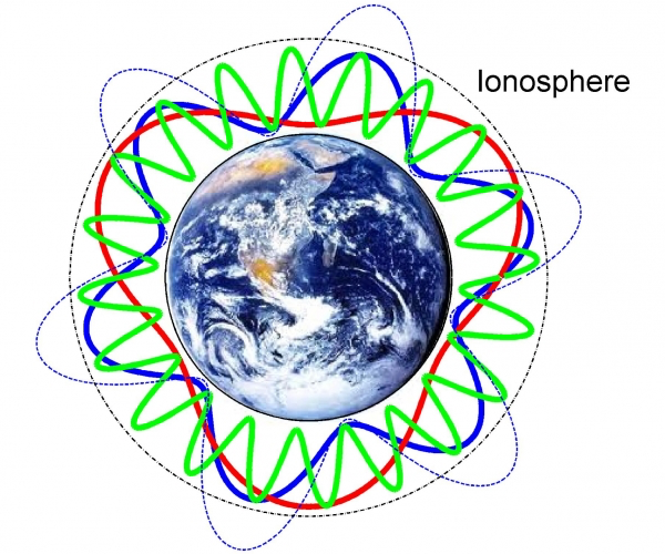
But there is another region of the Earth that is opaque to (at least some) radio waves. The ionosphere is the region of the atmosphere in which incoming solar radiation ionises the atmospheric gases (mentioned previously in 31. Earth’s atmosphere). It lies between approximately 60 to 1000 km altitude. Since ionised gas conducts electricity, low frequency radio waves cannot pass through it (higher frequencies oscillate too rapidly for the ionised particles to respond).

Radio waves with wavelengths longer than about 30 metres—or frequencies below about 10 MHz—are thus trapped in the atmosphere between the Earth’s surface and the ionosphere. This forms a waveguide which can carry so-called shortwave radio signals around the world, alternately bouncing off the ionosphere and the Earth’s surface.
There are also natural sources of low frequency radio waves. Lightning flashes in storm systems produce huge discharges of electrical energy, and the sudden release of this energy generates radio waves. If you’ve ever listened to a radio during a thunderstorm you’ll be familiar with the bursts of static caused by strokes of lightning. Lightning generates broadband radio emissions, meaning it covers a wide range of radio frequencies, including the very low frequencies that are guided by the ionospheric waveguide.
Atmospheric scientists measure the amount of lightning around the world by monitoring tiny changes in the Earth’s magnetic field, of the order of picoteslas, caused as these radio waves pass by. The sensitive detectors they use can detect lighting strikes anywhere on the planet. There are a few specific radio frequencies at which the lightning strikes turn out to be especially strong. The following plot shows the intensity of magnetic field fluctuations as a function of radio frequency.
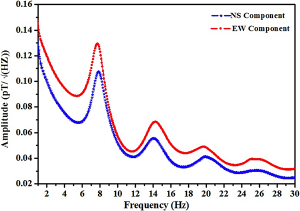
The first peak in the observed radio spectrum is at 7.8 Hz, followed by peaks at 14.3 Hz, 20.8 Hz, and roughly every 6.5 Hz thereafter. People familiar with wave theory will recognise from the pattern that these are likely resonance frequencies, with a fundamental mode at 7.8 Hz, followed by overtones. A wave resonance occurs when an exact number of wavelengths fits into a confined cavity. The wave propagates and bounces around and, because of the precise match with the cavity size, reflected waves end up with peaks and troughs in the same physical position, reinforcing one another. So at the specific resonance frequency, the wave builds up in intensity, while at other frequencies the waves self-interfere and rapidly die down. These resonance frequencies, which are measured at many research stations around the world, are known as Schumann resonances.
The Irish physicist George Francis FitzGerald first anticipated the existence of Schumann resonances in 1893, but his work was not widely circulated. Around 1950, the German physicist Winfried Otto Schumann performed the theoretical calculations that predicted the resonances may be observable, and made efforts to observe them. But it was not until 1960 that Balser and Wagner made the first successful observations and measurements of Schumann resonances.[2]
What causes the radio waves produced by lightning flashes to have a resonance at 7.8 Hz? Well, radio waves travel at the speed of light, so let’s divide the speed of light by 7.8 to see what the wavelength is: the answer is 38,460 km. If you’ve been paying attention to many of these articles, you’ll realise that this is very close to the circumference of the Earth.
Radio waves with a frequency of 7.8 Hz are travelling around the world in the waveguide formed by the Earth and the ionosphere, and returning one wavelength later to constructively interfere and reinforce themselves, producing a measurable peak in Earth’s magnetic field fluctuations at 7.8 Hz. The resonance peak is broad and a little different to 7.5 Hz (the speed of light divided by the circumference of the Earth) because the geometry of a spherical cavity is more complicated than a simple circular loop – effectively some propagation paths are shorter because the waves don’t all take a great circle route.
So Schumann resonances are an observed phenomenon that has a natural explanation – if the Earth is a globe.
If the Earth were flat, then any ionosphere above it would be flat as well, and would still form a waveguide for low frequency radio waves. However it would not be a closed waveguide. Radio waves would propagate out the edges and be lost to space, meaning there would be no observable magnetic field resonances at all. And even if there were an opaque radio wall of some sort at the edge of the flat Earth, the size and geometry of the resulting cavity would be different, resulting in a different set of resonance frequencies, more akin to the frequencies of a vibrating disc, which are not evenly spaced like the observed Schumann resonances.
And so Schumann resonances provide another proof that the Earth is a globe.
References:
[1] Shanmugam, M. “Investigation of Near Earth Space Environment”. Ph.D. Thesis, Manonmaniam Sundaranar University, 2016. https://www.researchgate.net/publication/309209580_Investigation_of_Near_Earth_Space_Environment
[2] Balser, M., Wagner, C. “Observations of Earth–Ionosphere Cavity Resonances”. Nature, 188, p. 638-641, 1960. https://doi.org/10.1038/188638a0
Randomly, I happened to encounter someone named “Shanmugam” yesterday for the first time, never having seen the name, and now I encounter it here.
I knew about the reflection of shortwave radio from the ionosphere, but I never thought to consider how it would (not) work on a flat Earth. Thanks.
At first I thought that you were badly misspelling ‘Schumann’. ☺
I’m a bit puzzled by the assertion that transmission lines will carry electromagnetic waves “up to frequencies of around 30 kHz”. Simple parallel wires used to be common for long-, medium- and even short-wave radio (hundreds of kHz to tens of MHz), and coaxial cables are routinely used for VHF (100 MHz) and UHF (hundreds of MHz). Over about 1 GHz you need very carefully designed coax cables, but they are routinely used for (say) the cable from a satellite TV antenna, which carries signals at between 1 and 2 GHz (a quick internet search didn’t find any specific frequencies).