When architects design and construction engineers build towers, they make them vertical. By “vertical” we mean straight up and down or, more formally, in line with the direction of gravity. A tall, thin structure is most stable if built vertically, as then the centre of mass is directly above the centre of the base area.
If the Earth were flat, then vertical towers would all be parallel, no matter where they were built. On the other hand, if the Earth is curved like a sphere, then “vertical” really means pointing towards the centre of the Earth, in a radial direction. In this case, towers built in different places, although all locally vertical, would not be parallel.
The Humber Bridge spans the Humber estuary near Kingston upon Hull in northern England. The Humber estuary is very broad, and the bridge spans a total of 2.22 kilometres from one bank to the other. It’s a single-span suspension bridge, a type of bridge consisting of two tall towers, with cables strung in hanging arcs between the towers, and also from the top of each tower to anchor points on shore. (It’s the same structural design as the more famous Golden Gate Bridge in San Francisco.) The cables extend in both directions from the top of each tower to balance the tension on either side, so that they don’t pull the towers over. The road deck of the bridge is suspended below the main cables by thinner cables that hang vertically from the main cables. The weight of the road deck is thus supported by the main cables, which distribute the load back to the towers. The towers support the entire weight of the bridge, so must be strong and, most importantly, exactly vertical.

The towers of the Humber Bridge rest on pylons in the estuary bed. The towers are 1410 metres apart, and 155.5 metres high. If the Earth were flat, the towers would be parallel. But they’re not. The cross-sectional centre lines at the tops of the two towers are 36 millimetres further apart than at the bases. Using similar triangles, we can calculate the radius of the Earth from these dimensions:
Radius = 155.5×1410÷0.036 = 6,090,000 metres
This gives the radius of the Earth as 6100 kilometres, close to the true value of 6370 km.

If this were the whole story, it would pretty much be case closed at this point. However, despite a lot of searching, I couldn’t find any reference to the distances between the towers of the Humber Bridge actually being measured at the top and the bottom. It seems that the figure of 36 mm was probably calculated, assuming the curvature of the Earth, which makes this a circular argument (pun intended).
Interestingly, I did find a paper about measuring the deflection of the north tower of the Humber Bridge caused by wind loading and other dynamic stresses in the structure. The paper is primarily concerned with measuring the motion of the road deck, but they also mounted a kinematic GPS sensor at the top of the northern tower[1].

The authors carried out a series of measurements, and show the results for a 15 minute period on 7 March, 1996.
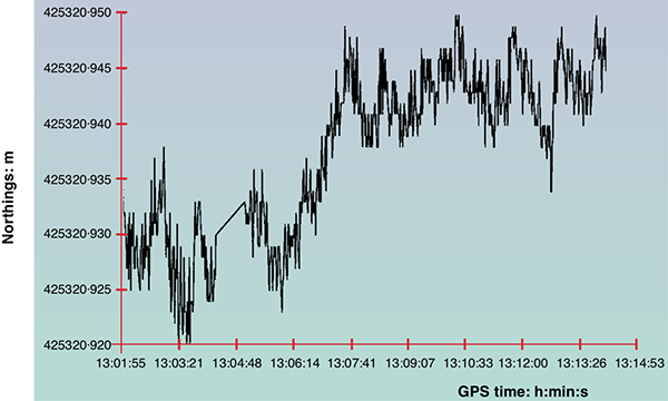
From the graph, we can see that the tower wobbles a bit, with deflections of up to about ±10 mm from the mean position. The authors report that the kinematic GPS sensors are capable of measuring deflections as small as a millimetre or two. So from this result we can say that the typical amount of flexing in the Humber Bridge towers is smaller than the supposed 36 mm difference that we should be trying to measure. So, in principle, we could measure the fact that the towers are not parallel, even despite motion of the structure in environmental conditions.
A similar result is seen with the Severn Bridge, a suspension bridge over the Severn River between England and Wales. It has a central span of 988 metres, with towers 136 metres tall. A paper reports measurements made of the flexion of both towers, showing typical deflections at the top are less than 10 mm[2].
Okay, so we could in principle measure the mean positions of the tops of suspension bridge towers with enough precision to establish that the towers are further apart at the top than the base. A laser ranging system could do this with ease. Unfortunately, in all my searching I couldn’t find any citations for anyone actually doing this. (If anyone lives near the Humber Bridge and has laser ranging equipment, climbing gear, a certain disregard for authority, and a deathwish, please let me know.)
Something I did find concerned the Verrazzano-Narrows Bridge in New York City. It has a slightly smaller central span than the Humber Bridge, with 1298 metres between its two towers, but the towers are taller, at 211 metres. The tops of the towers are reported as being 41.3 mm further apart than the bases, due to the curvature of the Earth. There are also several citations backing up the statement that “the curvature of the Earth’s surface had to be taken into account when designing the bridge” (my emphasis).[3]

So, this prompts the question: Do structural engineers really take into account the curvature of the Earth when designing and building large structures? The answer is—of course—yes, otherwise the large structures they build would be flawed.
There is a basic correction listed in The Engineering Handbook (published by CRC) to account for the curvature of the Earth. Section 162.5 says:
The curved shape of the Earth… makes actual level rod readings too large by the following approximate relationship: C = 0.0239 D2 where C is the error in the rod reading in feet and D is the sighting distance in thousands of feet.[4]
To convert to metric we need to multiply the constant by the number of feet in a metre (because of the squared factor), giving the correction in metres = 0.0784×(distance in km)2. What this means is that over a distance of 1 kilometre, the Earth’s surface curves downwards from a perfectly straight line by 78.4 millimetres. This correction is well known among civil and structural engineers, and is applied in surveying, railway line construction, bridge construction, and other areas. It means that for engineering purposes you can’t treat the Earth as both flat and level over distances of around a kilometre or more, because it isn’t. If you treat it as flat, then a kilometre away your level will be off by 78.4 mm. If you make a surface level (as measured by a level or inclinometer at each point) over a kilometre, then the surface won’t be flat; it will be curved parallel to the curvature of the Earth, and 78.4 mm lower than flat at the far end.
An example of this can be found at the Volkswagen Group test track facility near Ehra-Lessien, Germany. This track has a circuit of 96 km of private road, including a precision level-graded straight 9 km long. Over the 9 km length, the curvature of the Earth drops away from flat by 0.0784×92 = 6.35 metres. This means that if you stand at one end of the straight and someone else stands at the other end, you won’t be able to see each other because of the bulge of the Earth’s curvature in between. The effect can be seen in this video[5].
One set of structures where this difference was absolutely crucial is the Laser Interferometer Gravitational-Wave Observatory (LIGO) constructed at two sites in Hanford, Washington, and Livingston, Louisiana, in the USA.

LIGO uses lasers to detect tiny changes in length caused by gravitational waves from cosmic sources passing through the Earth. The lasers travel in sealed tubes 4 km long, which are under high vacuum. Because light travels in a straight line in a vacuum, the tubes must be absolutely straight for the machine to work. The tubes are level in the middle, but over the 2 km on either side, the curvature of the Earth falls away from a straight line by 0.0784×22 = 0.314 metres. So either end of the straight tube is 314 mm higher than the centre of the tube. To build LIGO, they laid a concrete foundation, but they couldn’t make it level over the distance; they had to make it straight. This required special construction techniques, because under normal circumstances (such as Volkswagen’s track at Ehra-Lessien) you want to build things level, not straight.[6]
So, the towers of large suspensions bridges almost certainly are not parallel, due to the curvature of the Earth, although it seems nobody has ever bothered to measure this. But it’s certainly true that structural engineers do take into account the curvature of the Earth for large building projects. They have to, because if they didn’t there would be significant errors and their constructions wouldn’t work as planned. If the Earth were flat they wouldn’t need to do this and wouldn’t bother.
UPDATE 2019-07-10: NASA’s Jet Propulsion Laboratory has announced a new technique which they can use to detect millimetre-sized shifts in the position of structures such as bridges, using aperture synthesis radar measurements from satellites. So maybe soon we can have more and better measurements of the positions of bridge towers![7]
References:
[1] Ashkenazi, V., Roberts, G. W. “Experimental monitoring of the Humber bridge using GPS”. Proceedings of the Institution of Civil Engineers – Civil Engineering, 120, p. 177-182, 1997. https://doi.org/10.1680/icien.1997.29810
[2] Roberts, G. W., Brown, C. J., Tang, X., Meng, X., Ogundipe, O. “A Tale of Five Bridges; the use of GNSS for Monitoring the Deflections of Bridges”. Journal of Applied Geodesy, 8, p. 241-264, 2014. https://doi.org/10.1515/jag-2014-0013
[3] Wikipedia: “Verrazzano-Narrows Bridge”, https://en.wikipedia.org/wiki/Verrazzano-Narrows_Bridge, accessed 2019-06-30. In turn, this page cites the following sources for the statement that the curvature of the Earth had to be taken into account during construction:
[3a] Rastorfer, D. Six Bridges: The Legacy of Othmar H. Ammann. Yale University Press, 2000, p. 138. ISBN 978-0-300-08047-6.
[3b] Caro, R.A. The Power Broker: Robert Moses and the Fall of New York. Knopf, 1974, p. 752. ISBN 978-0-394-48076-3.
[3c] Adler, H. “The History of the Verrazano-Narrows Bridge, 50 Years After Its Construction”. Smithsonian Magazine, Smithsonian Institution, November 2014.
[3d] “Verrazano-Narrows Bridge”. MTA Bridges & Tunnels. https://new.mta.info/bridges-and-tunnels/about/verrazzano-narrows-bridge, accessed 2019-06-30.
[4] Dorf, R. C. (editor). The Engineering Handbook, Second Edition, CRC Press, 2018, ISBN 978-0-849-31586-2.
[5] “Bugatti Veyron Top Speed Test”. Top Gear, BBC, 2008. https://youtu.be/LO0PgyPWE3o?t=200, accessed 2019-06-30.
[6] “Facts about LIGO”, LIGO Caltech web site. https://www.ligo.caltech.edu/page/facts, accessed 2019-06-30.
[7] “New Method Can Spot Failing Infrastructure from Space”, NASA JPL web site. https://www.jpl.nasa.gov/news/news.php?feature=7447, accessed 2019-07-10.
Why not measure angle on the suspension bridges instead? From the bases, use a level to confirm the towers are perfectly vertical, which also heads off the “but the towers are tilted” argument. From there, project a level horizontal line at a known reference height from one tower to the other. It should hit the other tower at a slightly higher point. From there, the angle between the projected line and an imaginary line between the two bases at a known height can be measured, or alternately, measure the difference between the known reference height and the projected point at the destination tower.
This should produce a measurable result without having to do anything dangerous/illegal. As an added bonus, measuring the difference between the known reference height and the projected point should result in a visibly larger height difference than the 36mm horizontal difference quoted for the other method of measurement.
That’s a good idea. I wonder if there’s some place local to me where I can do such an experiment without too much trouble. There are no large suspension bridges where I live. In principle you could do it with any two buildings separated by a roughly a kilometre or more, but you’d need precision surveying gear to measure the altitudes of the laser at the source and the projected spot.
Thinking about this some more, I think it’s possible to conduct the experiment without needing to know the exact altitude, though of course a very precise level would still be needed.
Once the towers are confirmed to be perfectly vertical, a point is chosen on one tower as the origin point of the laser. This origin point should be marked. At the second tower, the projected point is marked. Once that’s done, the laser is removed from the first tower and taken over to the second tower. The laser is mounted at the point marked by the projected beam, and then aimed back at the first tower.
If the Earth were flat, this should result in the laser hitting the origin point on the first tower. However, on a spherical Earth, projecting from the first tower to the second tower should result in an elevated point on the second tower. Projecting from the second tower back to the first should then result in a second elevated point. Since a round trip is being measured, this should double the amount of detectable variation. Continuing to mark points back and forth in this fashion will progressively increase the detectable variance, as the laser effectively zigzags back and forth.
With this method, the only altitude (actually elevation) measurements needed are preliminary elevation measurements at each tower to ensure their bases are close enough in elevation to not require anything more complicated than a step ladder to reach the points. Such elevation measurements would only need to be accurate to within 1-2 meters–just enough to ensure the experiment can be conducted from ground level at both ends. It is possible to skip the elevation measurement, but using the leveled laser to scout out possible locations would be a slower, more tedious process.
Some random thoughts: A perfectly vertical mirror could be used as a reflector at the second tower. If setup properly, this could allow measurements to be taken at the first tower. Also, if one must use an off-the-shelf laser, a cradle can be used to support the laser, and the laser can be rotated within the cradle to ensure the body of the laser is coaxial to the beam. If not, marking where the beam hits as the laser is rotated should result in a circle. The center of that circle is where the beam would hit if it were truly coaxial to the body of the laser.
Good idea, because the towers could very well be tilted.
If each tower is carrying a symmetric span, vertical IS optimal. But if for some reason geography limited the placement of the towers to carrying an asymmetric span, then being tilted would be optimal. (To balance out the force vectors.)
Light does not travel straight in a vacuum. It is bent by gravity.
Although you could claim that the light goes straight, but space itself is bent.
(This is kind of the whole reason LIGO exists in the first place)
But dealing with non-euclidean space would just unnecessarily complicate your argument I think. The definitions of terms like “parallel” and “orthogonal” start breaking down a bit.
Or you could just calculate the deviation due to the gravity of the Earth.
I suspect you would find it negligible compared to Earth’s curvature.
Light can travel nearly 3,000km in 0.01 seconds. In Earth gravity, light would fall less than 1mm during that 0.01 seconds. Doing the math for light traveling across a 3km span, I’m calculating a drop of about 1 millionth of a millimeter. At the distances discussed in the article, the effect of gravity on light can be safely ignored without any appreciable effect on measurements.
Oh yes. I know it’s negligible for most most purposes.
But it’s also nonzero. You have to be aware of an effect before deciding to ignore it or not. After all, a lot of the effects being used in these proofs, while easily detectable to instruments and careful measurement, are negligible enough to the human eye, that we ignore them too. And as subtle an effect as gravitational lensing is; it is still an important effect, especially in astronomy. Light does not go straight in a vacuum!
earths radius = 6378.170 km or roughly 41million meters
imagine hypothetically , taking 41m chinese around the planet with a piece of string ,now . increase strings lenght by 15m .
question , how high that could that string be lifted ,
a, nothing much
b,waist high
c, above their heads
Light can travel nearly 3,000km in 0.01 seconds. In Earth gravity, light would fall less than 1mm during that 0.01 seconds. Doing the math for light traveling across a 3km span, I’m calculating a drop of about 1 millionth of a millimeter. At the distances discussed in the article, the effect of gravity on light can be safely ignored without any appreciable effect on measurements.
A couple more complicating factors.
If you’re measuring the distance between the towers, top and bottom, are the front and back surfaces parallel? In the Severn Bridge, to take an example, the towers are made of steel plate, which is an inch thick (25mm) at the base, progressively reducing to 9/16 inch (14mm) at the top. As far as I know, the towers are designed so that the outside of the tower is the same size all the way up, but the interior cavity gets wider as you go up; but this is certainly not axiomatic!
Whether you use this method or the local level method, the vertical (or horizontal) you measure at each end will be affected by the direction of local gravity, which depends on topography. Not very much, but it’s another of those things that needs to be calculated in order to be declared negilgible.
dont forget to allow for heat of sun. bridge beams are measured at different times so the same or similar distortion is apparent .
the differences each beam is scary which is why beams have both fixed points and slide or rollers to allow for both expansion n contraction an different lenghts depending on time of day .
to overcome this , engineers survey at 3 different times for each beam and extrapolate or average the error or distance off design centre line for each and move beams sideways until design placement is correct
the same applies for vertical towers the sunny side is longer just as cold side is shorter
hope this throws some light onto care surveykurs n engineers take in measuring
Science YouTuber Tom Scott thinks the same as you: https://youtu.be/dLQQ1F7hplA . He mentions the curvature, although the main topic is how they keep the cables from corroding. Readers of this blog will probably enjoy his channel.
why would they made a curved bridge over flat water other than to make it structuraly more stable?
In the middle, the minimum height is determined by the size of vessels that must pass underneath. At the ends, anything other than ground level introduces a requirement to build an embankment or excavate a cutting. If the minimum clearance for boats mandates a bridge much higher than ground level at the ends, a curved bridge is lilely to be easier and cheaper than building a large embankment.
That said, although a suspension bridge like that over the Humber could be made flat, it probably is more stable if it has a slight arch. The Severn bridge – the same design as the Humber bridge, but a bit shorter – has a slight arch to it, even though at one end the road comes onto it from a cutting in the cliff.
The towers would still be further apart at the top than the bottom even if the Earth was a cube. Towers should always point to the centre of mass of the planet they’re on, i.e. not straight down for a cube but towards its centre.
👍
If the Earth were a cube, and gravity worked according to Newton’s law – down is always towards the centre of the planet – then the faces of the cube would look flat, but feel like great bowls. Everything would slope down towards the middle of each face, and near the edge, the surface would be tilted at 45 degrees. (Near the vertex, the angle of tilt rises to a massive 54.7 degrees!) Apart from everything else, you’d be outside the atmosphere if you travelled more than a thousand miles from the centre of any face. And don’t say the planet might be a cube, but with these features smoothed off – that would be a globe.
Basically, if the Earth is a cube, then gravity doesn’t work like that – pointing to the centre of the planet. So you cannot reasonably say that on a cubical Earth, bridge towers would tilt a similar amount.
Hi Philip,
thanks for this. I’m not suggesting that the Earth is a cube, I don’t think it is.
What I am suggesting is that the planet doesn’t have to be round for gravity to necessitate bridge towers to be further apart at the top.
I’m pretty sure that gravity does act towards the centre of mass of a cube.
Oh goodness. This could get out of hand, but…
Yes, in *our* world, where gravity works on something resembling Newtonian lines, “down” on a cubical body does indeed point at the centre of mass of the cube.
My point was that if you posit some shape not approximating a sphere, such as a cube, you also have to posit gravity working according to some set of laws that aren’t like Newton’s. Otherwise you get a lot of effects that we don’t observe on Earth. So IF you posit a non-spherical Earth, you ALSO have to posit non-Newtonian gravity, and your point about the centre of mass of the cube ceases to be valid. Bridge towers on a cubical Earth wouldn’t be expected to diverge, not because Newtonian gravity doesn’t work that way, but because a cubical Earth couldn’t have Newtonian gravity and still resemble Earth.
OK. I apologise. I replied without doing the calculation. I take back my last reply.
No, gravity does NOT point towards the centre of mass of a cube. If you are far enough away, it does; but if you are close to one of the faces it doesn’t. Memories of first-year geology lectures suggest that when you are close to the surface, the bits that stick up (relative to the sphere) pull the plumb line off true.
When I was a student, I might have attempted an analytic solution with a differential equation and stuff. I know I couldn’t manage that now, so I put a finite element model in a spreadsheet. 9261 (21 cubed) identical masses at points (-10,-10,-10) to (10,10,10) in the obvious distribution. I then looked at the direction of gravity at (0,0,11) – the middle of a face, so it would be towards the centre by symmetry – and (0,1,11) – one unit away. Since the centre of this cube is at (0,0,0), the angle between the perpendicular and the line to the centre of the face is arc sin (1/11) = about 5.2°. When I added up the effect of gravity of each of the 9261 elements at this point, I got a vector that was ony 2.9° from the perpendicular.
My conclusion is that if the Earth were a cube, AND gravity obeyed Newton’s law, bridge towers would diverge by about half what you’d expect with a spherical Earth.
But my original point stands: for a cubical world to resemble Earth at all, gravity CAN’T operate according to Newton’s law because planar faces wouldn’t feel flat; rather, they’d slope up from deep ocean basins in the centres of faces to huge ridges and peaks at the edges and vertices that stuck right out of the atmosphere.
Hi Philip,
many thanks for going to the trouble to explain all this, and do the calculations which I have to admit are beyond my capabilities.
I think we’re on the same page now.
Terry
I’m rereading some of these, and I want to say I’m really impressed by the amount of searching and analysis you’re willing to do.
This post is great. I know that flat-earthers sometimes talk about large bridges, and here you’re looking up information on bridges, and carefully going through all the numbers that are and are not available. Since it’s hard to get measurements of everything we’re looking for, you looked into other sources of information and quoted engineering manuals, and cited the LIGO as an engineered structure that is designed to account for the globe in a conspicuous way.